
生物力学_Failure, Fracture, Fatigue
Failure, Fracture, Fatigue
- Failure
- Failure Theory
- By material or structural failure, it is meant that the material either ruptures so that it can no longer support any load / undergoes excessive permanent deformation(yielding)
- ductile
- yield before fracture
- generally deform through shear in response to generalized states of stress
- brittle
- fracture before yield
- Brittle systems are weak in tension, and the generalized failure criterion is based on thenormal stress, or principal stresses, reaching the fracture stress or ultimate strength of the material
- Yield Strength
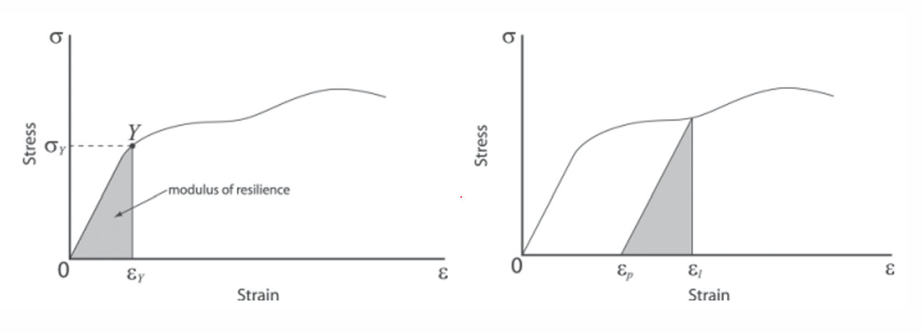
- The modulus of resilience for a material is defined as the energy that is stored in a material until the onset of yielding
- Once yielding has occurred in a material
- only elastic strain can be recovered upon unloading
- plastic strain results in permanent deformation that is not recovered upon removal of the stress
- The modulus of resilience for a material is defined as the energy that is stored in a material until the onset of yielding
- Yield Surfaces
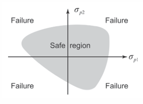
- A yield surface is the surface within the space of stresses that defines the boundary between elastic and plastic behavior for a material.
- The state of stress that is contained inside this surface represents elastic behavior of the material.
- The boundary represents stress states at which the material has reached its yield strength and is behaving in a plastic manner
- 面里面是弹性,到达边界开始塑性形变
- Failure Theories
- Maximum Shear Stress Theory
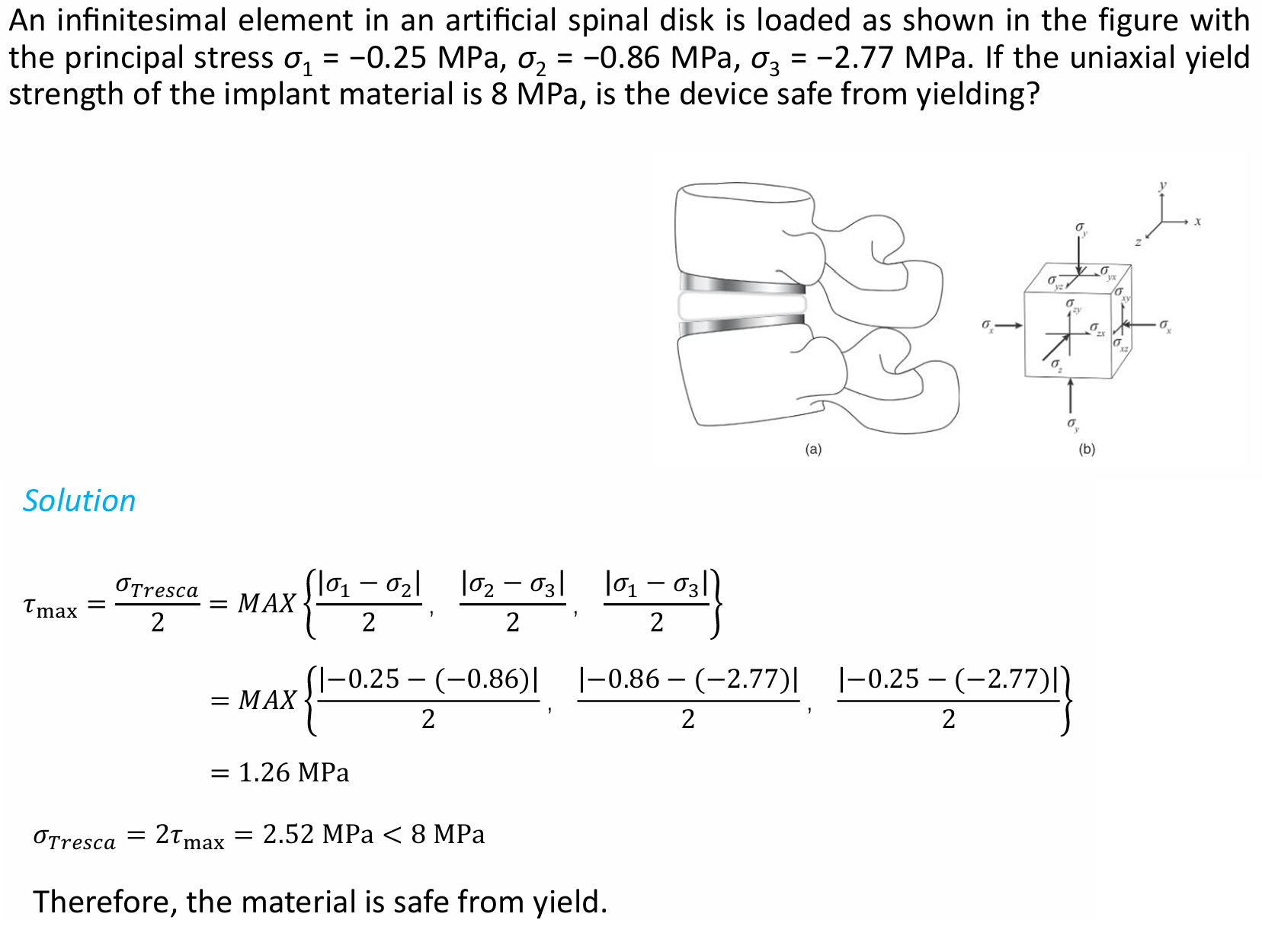
- The maximum shear stress theory (Tresca yield criterion) is used to predict yielding and therefore is applicable to ductile materials
- These shear processes utilize dislocation slip systems to accommodate plastic deformation once the elastic range of deformation is exhausted.
- Yielding (slip) occurs when the maximum shear stress reaches the yield stress determined from the uniaxial tensile test.
- For the biaxial stress state
- σ3 = 0, and σ0 = σyp = uniaxial flow or yield strength
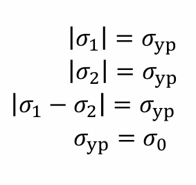
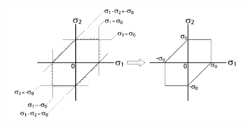
- the general equations for maximum shear stress using the principal stress differences defined by the Tresca yield criteria are plotted in σ1 − σ2 space to generate the boundary of the yield surface
- The boundary of the yield surface (hexagon) is defined by the equations below
- For cases where the stresses are less than the maximum shear yield criteria, the material will be contained within the envelope and will be safe from plastic deformation.
- For three-dimensional space
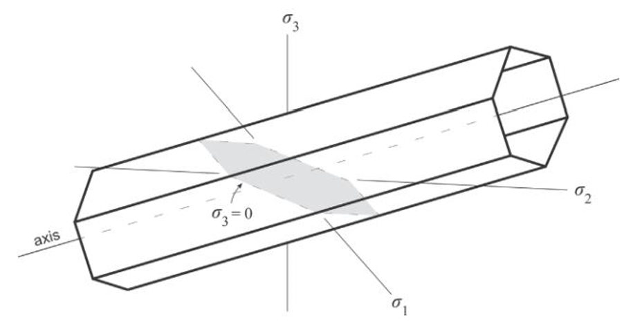
- the yield surface is a hexagonal prism with a hexagon projected down the hydrostatic axis where σx = σy = σz
- The general three-dimensional Tresca yield criterion is founded upon the notion that the plane of greatest shear stress dictates the maximum overall shear stress, and is given as
- the yield surface is a hexagonal prism with a hexagon projected down the hydrostatic axis where σx = σy = σz
- example
- 图
- 图
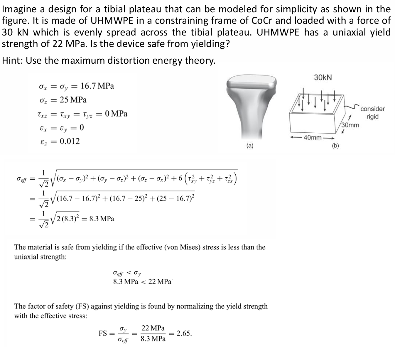
- Maximum Distortion Energy Theory
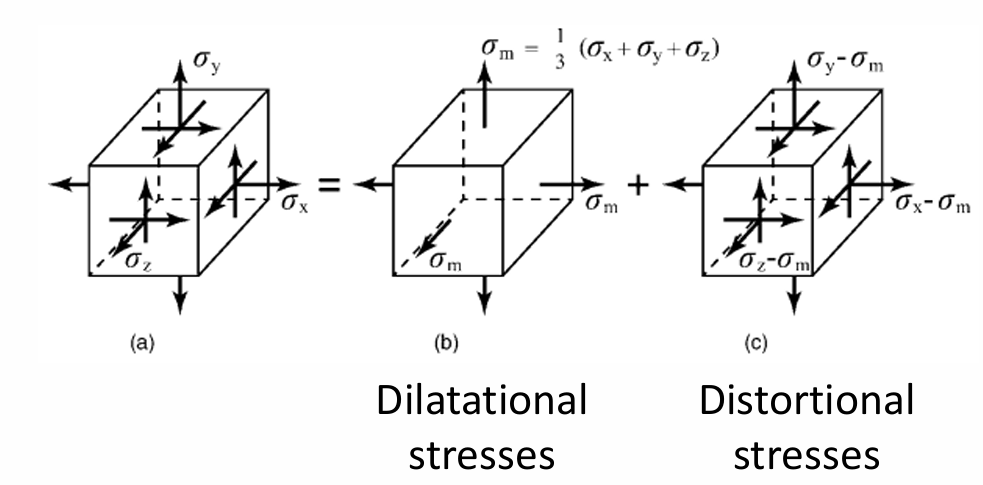
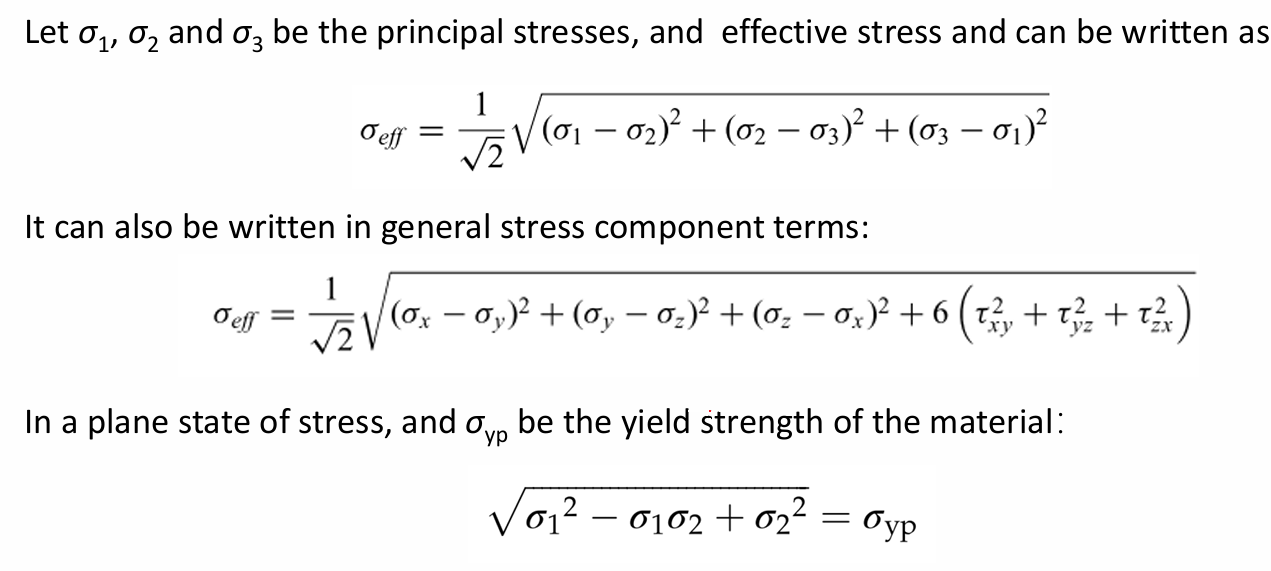
- The maximum distortion energy theory (von Mises yield theory) is a widely accepted criterion that states the conditions for yielding of ductile materials
- This theory assumes that yielding occurs when the maximum distortional energy associated with the combined stress state reaches the uniaxial yield strength
- 公式
- example
- 图
- 图
- Maximum Normal Stress Theory
- This is a relatively simple theory to implement, and it applies both for ductile and brittle materials
- The maximum normal stress theory is based on the assumption that failure by yielding occurs whenever the largest principal stress is equal to the yield strength σyp , or that failure by rupture occurs whenever the largest principal stress is equal to the ultimate strength σult of the material
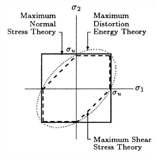
- Comparison of Failure Theories
- For a given theory, failure occurs if the stress level falls on or outside the closed boundary representing that theory
- The maximum shear stress theory is always more conservative and safer
- The failure theories reviewed here are valid for static loading conditions. These theories must be modified to account for dynamic or repeatedly applied loads that can cause fatigue
- For a given theory, failure occurs if the stress level falls on or outside the closed boundary representing that theory
- Maximum Shear Stress Theory
- Factor of Safety
- A structure must be designed to withstand the maximum possible stress level, called working stress, to which it will be subjected when it is put in service.
- To account for the effects of uncertainties, a stress level called the allowable stress must be set considerably lower than the ultimate strength of the material.
- The factor of safety (FS) against plastic deformation can be calculated from the ratio of the ultimate strength or uniaxial yield strength to the effective stress.
- Failure Theory
- Fracture
- basic
- Medical device fractures occur when cracks or sharp flaws cause a local extreme stress局部极端应力 that causes material breakdown, even under relatively mild loading conditions.
- Flaws or cracks can exist inherently固有 in the material or caused by manufacturing.
- Cracks can form during loading near sharp notches designed into the component, even if the component is flaw-free.
- Fracture mechanics helps prevent such failures through analysis.
- Fracture at Atomic Level
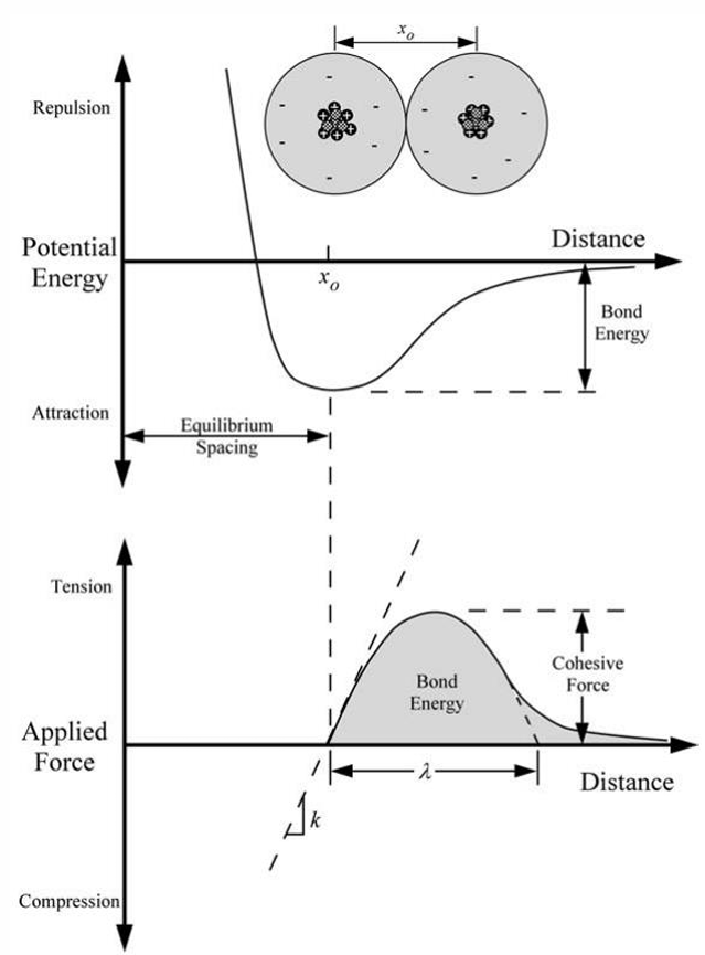
- Bond Energy
- Two atoms or a set of atoms are bonded together by cohesive energy or bond energy.
- Two atoms are fractured if the bonds between them are broken by externally applied tensile load.
- bond or cohesive energy
- 图 - potential energy and applied force show bond energy as area under the force-displacement curve
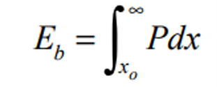
- formula
- x0 is the equilibrium spacing
- P is the applied force
- 图 - potential energy and applied force show bond energy as area under the force-displacement curve
- Cohesive Strength
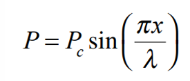
- The cohesive strength at the atomic level can be estimated by idealizing the interatomic force-displacement relationship as one half-period of a sine wave.
- force-displacement approximation
- formula
- λ is the characteristic separation distance from the figure
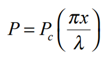
- for small displacement , the relationship is linear
- formula
- formula
- formula
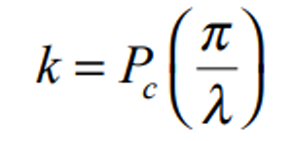
- bond stiffness i.e.the spring constant
- formula
- formula
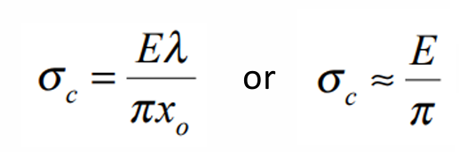
- convert to Young’s modulus and cohesive stress
- Multiplying by the number of bonds per unit area and the gage length x0 converts k to E and Pc to σc.
- formula
- Surface Energy
- Surface energy quantifies the disruption of intermolecular bonds that occurs when a surface is created.
- Also called surface free energy or interfacial free energy.
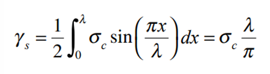
- Simple definition: work per unit area done by the force that creates the new surface.
- surface energy estimate
- formula
- formula
- The surface energy per unit area γs is one-half of the fracture energy because two surfaces are created when a material fractures.
- we can conclude that
- Bond Energy
- Stress Concentration
- Basic
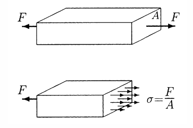
- Classic stress definition assumes
- the external force F is applied over a relatively large area rather than at a single point.
- the cross-sectional area is constant through the bar length.
- So, for a bar with cross-sectional area A subjected to tensile force F, stress is σ = F / A.
- Uniform stress is disturbed
- by holes, cracks, fillets, scratches, or notches.
- if the force is applied over a very small area.
- Stress distribution is no longer uniform at the section where discontinuity is present.
- Classic stress definition assumes
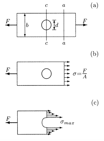
- Plate with a Hole
- 图
- Away from the hole, stress distribution is assumed uniform, at section aa, σ = F / A.
- At section cc through the center of the hole, average stress is σ = F / (A - Ah).
- A - Ah is always less than A, so average stress at section cc is greater than uniform stress at section aa.
- Stress at section cc is not uniform. Stress is maximum along the edges of the hole. This phenomenon is known as stress concentration应力集中.
- 图
- Formula
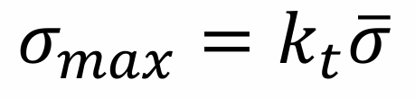
- There are empirical formulas经验公式 to calculate maximum stresses developed due to stress concentrators.
- general relationship
- formula
- maximum stress σmax
- average stress σ
- kt is the stress concentration factor
- formula
- safety
- A structure may fail unexpectedly due to stress concentration effects even when average stress is below fracture strength.
- The fracture or ultimate strength may be exceeded locally due to a stress concentrator.
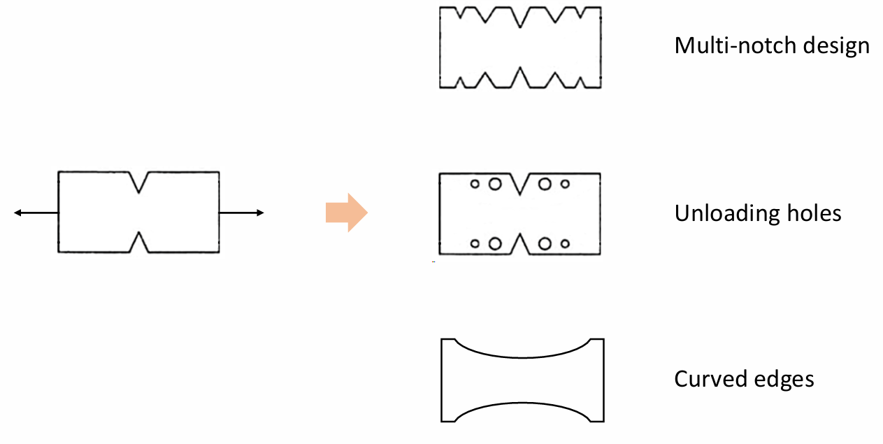
- Designs to Reduce Stress Concentration
- 图
- 图
- Basic
- Cracks as Extreme Stress Concentrators
- Why Do Cracks Weaken a Material
- The breaking strength falls by a greater factor than the reduction in cross-sectional area.
- 图 - cracked plate and glass show that crack tips dominate failure, not just missing area.
- Inglis Elliptical Crack
- In 1913, Inglis calculated stresses and strains in an elastic plate containing an elliptical crack.
- elliptical crack geometry
- semi-axes a and b
- applied stress σ is applied vertically
- plate width >> 2a
- plate height >> 2b
- stress at the tip of the major axis Point A
- σA = σ(1 + 2a / b)
- stress concentration factor
- kt = σA / σ
- when a = b, the hole is circular and kt = 3.0
- Sharp Crack Approximation
- As major axis a increases relative to b, the elliptical hole begins to look like a sharp crack.
- radius of curvature form
- σA = σ(1 + 2√(a / ρ))
- ρ = b^2 / a
- For a sharp crack
- a >> b
- a >> ρ
- σA = 2σ√(a / ρ)
- 裂纹越尖, ρ越小, 尖端应力越夸张
- Atomically Sharp Crack
- The sharp-crack equation predicts infinite stress at the tip of an infinitely sharp crack where ρ = 0.
- No material is capable of withstanding infinite stress.
- Metals can deform plastically, which blunts an initially sharp crack.
- Without plastic deformation, the minimum crack-tip radius is on the order of atomic radius.
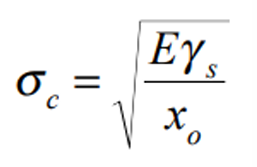
- substitute ρ = x0
- σA = 2σ√(a / x0)
- if fracture occurs when σA = σc
- σf = (Eγs / 4a)^(1/2)
- Why Do Cracks Weaken a Material
- Case Study
- Mechanoadaptive polysaccharide conjugates architect pro-healing microenvironments via dynamic stress redistribution in skin defects.
- Problem
- Tip stress concentration in linear wounds can impede wound healing.
- Static biomaterials do not fully match dynamic tissue remodeling.
- HADEX strategy
- adhesive bioconjugate platform composed of micrometer-sized polysaccharide-derived granules
- precise shaping and manipulation
- dynamically cross-linking adhesive driven by fluid convection
- Mechanics idea
- HADEX modulates stress distribution within wet linear wounds.
- HADEX restores tissue pretension.
- HADEX facilitates load transfer to regenerating tissue.
- stress concentration at wound edge is resolved into a more distributed stress layout
- Figure Notes
- 图 - applying dehydrated HADEX bioconjugates to wound absorbs biological substances.
- 图 - optimized wet wound adhesion remodels the mechanical microenvironment.
- 图 - finite element map shows high stress near wound edge before HADEX and lower concentrated stress after HADEX.
- 图 - in vivo rat and porcine skin incision models validate closure and healing.
- basic
- Fatigue
- Fatigue Definition
- Many structures, including machine parts and muscles and bones in the human body, are subjected to repeated loading and unloading.
- Loads that may not cause failure in a single application may cause fracture when applied repeatedly.
- Failure may occur after a few cycles or after millions of cycles.
- Fatigue life depends on
- amplitude of applied load
- physical properties of the material
- size of the structure
- surface quality of the structure
- operational conditions
- Fracture due to repeated loading is called fatigue疲劳.
- In mechanics, fatigue implies complete structural failure.
- Types of Fatigue
- Mechanical Fatigue
- Multiaxial Fatigue 多轴疲劳
- Thermal Fatigue
- Creep-Fatigue
- Thermomechanical Fatigue 热机械疲劳
- Corrosion Fatigue
- Contact/Fretting Fatigue 接触/微动疲劳
- Combinations of above
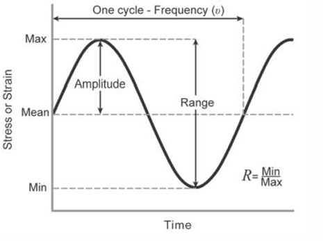
- concept of cyclic stress
- 图
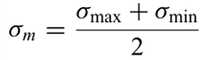
- Mean Stress
- The bar is first stressed to a level σm, a mean stress, considerably lower than ultimate strength σu.
- formula
- Stress Amplitude
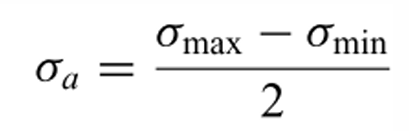
- The amplitude σa of the stress gives a maximum tensile stress of σmax = σm + σa.
- formula
- Stress Range
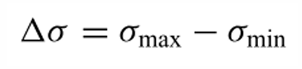
- The stress range is typically the dominant factor in progression of fatigue damage.
- formula
- R-ratio
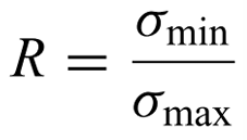
- For most materials, increased mean stress for equal stress amplitude shortens fatigue life.
- formula
- fully reversed loading
- R = -1
- tensile loading
- R ranges from 0 to 1, approaching the static limit
- fully compressive loading
- R > 1
- 平均拉应力越高, 越容易疲劳失效
- 对于以应变为主导机制的材料, 应变幅度成为疲劳寿命中的主导因素, 把stress改成strain就行
- Variable Amplitude Loading
- 图
- This reversible and periodic stress is applied until the bar fractures and the number of cycles (N) to fracture is recorded.
- 这种可逆且周期性的应力被施加,直到棒材断裂,并记录断裂时的循环次数(N).
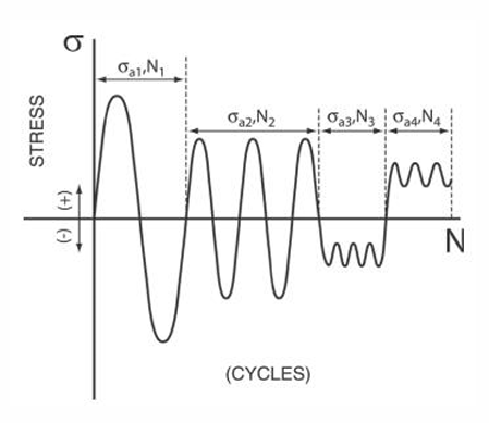
- The same terminology is utilized when the amplitude of loading is variable and the primary difference is that the parameters are then defined for specific intervals or cycles, Ni, of constant amplitude loading.
- 当载荷幅值可变时,使用相同的术语,主要区别在于参数随后是针对等幅载荷的特定区间或循环数Ni来定义的.
- Under variable amplitude loading, the definition of one cycle is not clear and hence reversals of stress are often considered.
- 在变幅载荷下,一个循环的定义并不明确,因此通常考虑应力的反向次数.
- In constant amplitude loading, one cycle equals two reversals.
- 在等幅载荷下,一个循环等于两次反向.
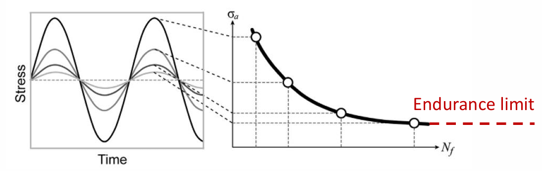
- This experiment is repeated on specimens having the same geometric and material properties by applying sinusoidal stresses of varying amplitude.
- 通过对具有相同几何和材料性能的试样施加不同幅值的正弦应力,重复该实验.
- 图
- 图
- Three Stages of Fatigue
- Nucleation of a crack by small amounts of inhomogeneous plastic deformation at a microscopic level.
- Slow growth of these cracks by cyclic stressing.
- Sudden fracture occurs when the cracks reach a critical size.
- Fatigue requires 3 ingredients on each cycle
- cyclic loading
- tensile stresses
- plastic strain
- Stress-Based Loading
- S-N Diagram
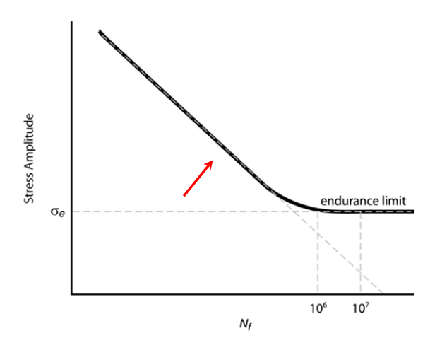
- The number of cycles to failure, Nf, depends on stress amplitude σa.
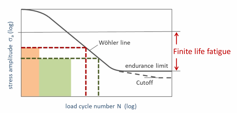
- An endurance limit is the cyclic stress level that enables infinite life in the material.
- 图 - S-N curve drops as stress amplitude increases and approaches an endurance limit.
- Endurance Limit 持久极限
- If a device is subjected to a stress below its endurance limit, the device is safe from fatigue failure.
- The endurance limit of most steels is 35-50% of the ultimate tensile strength.
- Endurance limit can be affected by
- surface finish
- stress concentrations
- heat treatment
- environment
- component design
- endurance limit is not a universal material constant
- If a device is subjected to a stress below its endurance limit, the device is safe from fatigue failure.
- Polymer Systems Used in Medical Devices
- 图
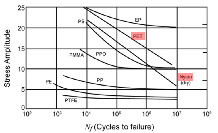
- Nylon and polyethylene terephthalate(PET) do NOT exhibit an endurance limit.
- Polyethylene(PE), polypropylene oxide(PPO), polystyrene(PS), polytetrafluoroethylene(PTFE), polypropylene(PP), polymethylmethacrylate(PMMA), and epoxy (EP) clearly exhibit an endurance limit.
- 图
- Low-Cycle vs High-Cycle Fatigue
- 图
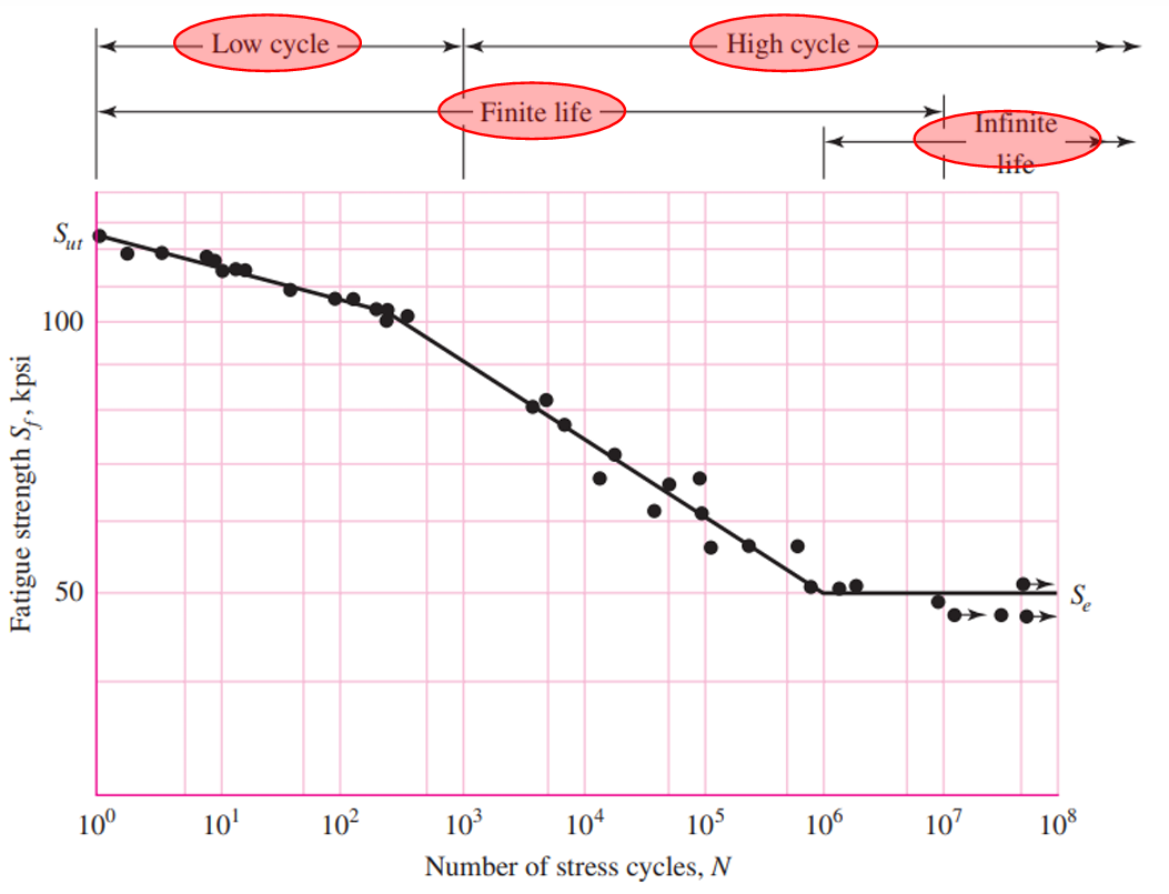
- Low-cycle fatigue
- caused by large plastic strains
- low number of load cycles before failure
- Nf = 1 to 10^3 cycles
- High-cycle fatigue
- mainly elastic deformation
- limited plastic deformation
- high number of load cycles
- Nf > 10^3 cycles
- For steels, the boundary between finite-life and infinite-life regions lies somewhere between 10^6 and 10^7 cycles.
- 图
- Basquin Equation
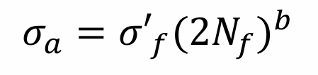
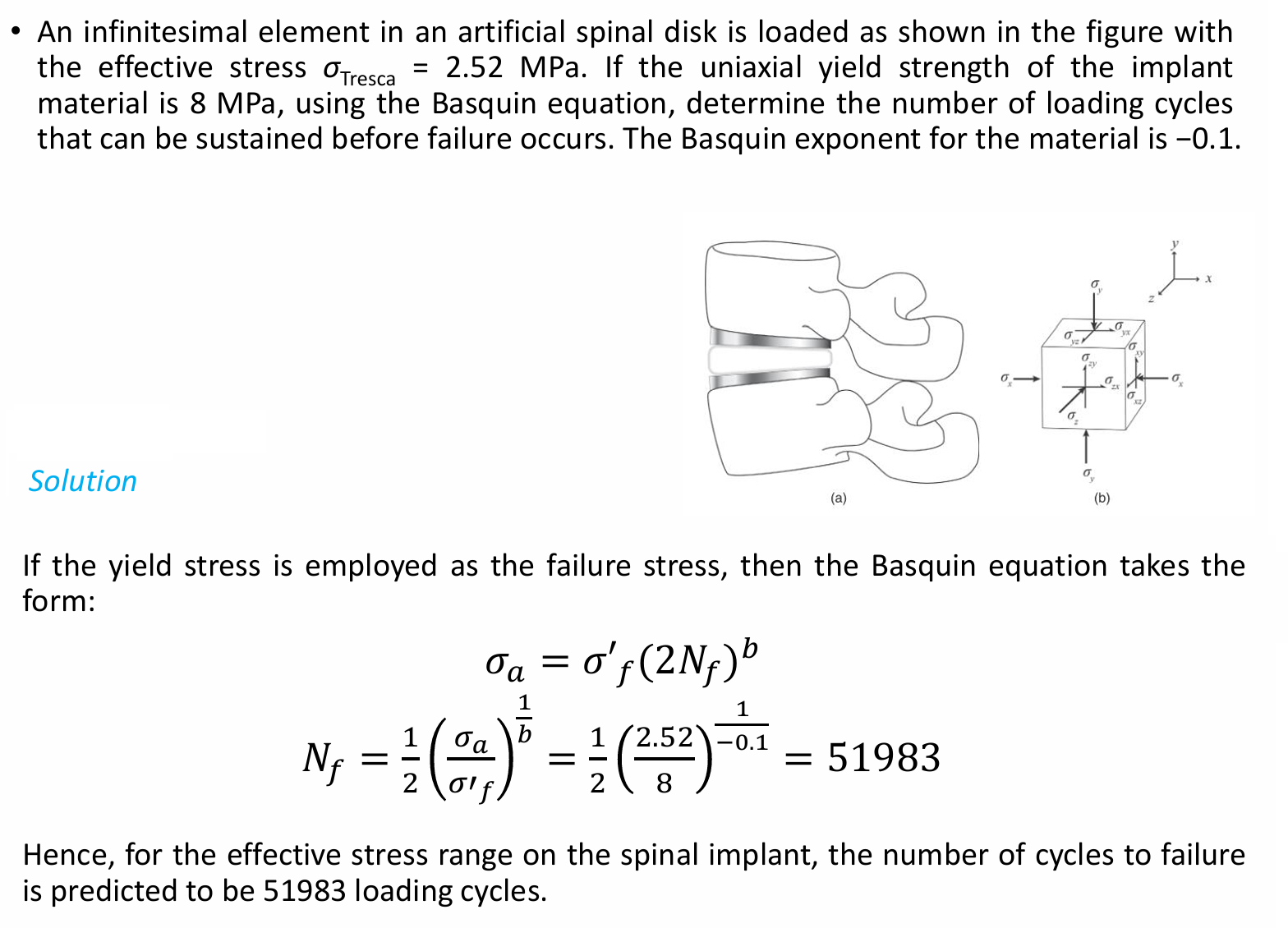
- The relationship between stress amplitude and number of cycles to failure is known as the Basquin equation.
- formula
- parameters
- σa - stress amplitude
- σ’f - failure stress for the material
- 2Nf - number of reversals to failure
- b - Basquin exponent
- The Basquin exponent is determined from the slope of stress amplitude versus number of cycles to failure on a linear-log plot.
- Typical b for most metal and polymer systems is between -0.05 and -0.10.
- Basquin equation assumes mean stress is zero, that is the specimen or component is undergoing fully reversed loading and that each cycle represents two reversals
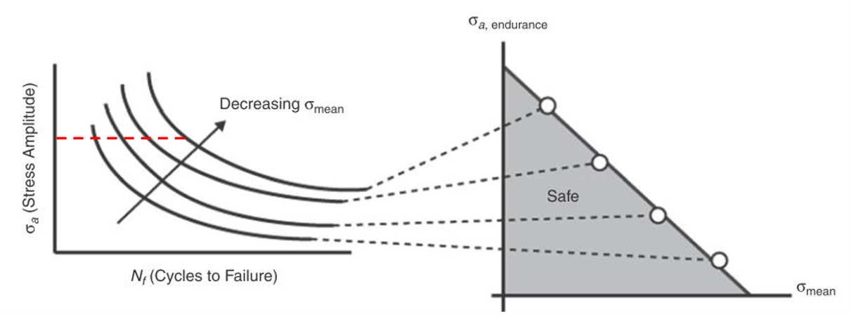
- As the mean stress of a fatigue cycle is increased, the number of cycles to failure and the endurance limit (if it exists) is decreased substantially.
- Example
- 图
- 图
- S-N Diagram
- Strain-Based Loading
- Use Cases
- Strain-based tests are used when a structural component is likely to experience fluctuations in displacement or strain.
- They are often used for components expected to undergo localized plastic strain, such as designs with notches or stress concentrations.
- The majority of strain-based fatigue tests use fully reversed applied strain conditions.
- Manson–Coffin Equation
- Cyclic strain data are represented analogously类似 to S-N characterization in stress-based testing.
- Total Strain Amplitude Δεa
- The total strain amplitude Δεa can be divided into
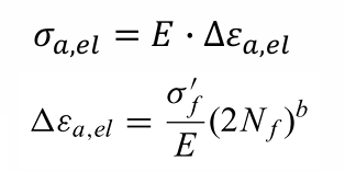
- elastic strain amplitude Δεa,el
- Hooke’s law + Basquin Equation,σ’f 疲劳强度系数, b 疲劳强度指数
- Hooke’s law + Basquin Equation,σ’f 疲劳强度系数, b 疲劳强度指数
- plastic strain amplitude Δεa,pl
- formula,ε’f 疲劳延性系数, c 疲劳延性指数
- formula,ε’f 疲劳延性系数, c 疲劳延性指数
- elastic strain amplitude Δεa,el
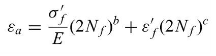
- total strain-life relation
- The total strain amplitude of the fatigue cycle is plotted against the number of cycles or load reversals to failure, and is found by summing the elastic and plastic components
- The total strain amplitude of the fatigue cycle is plotted against the number of cycles or load reversals to failure, and is found by summing the elastic and plastic components
- Transition Between Low-Cycle and High-Cycle
- high-cycle fatigue
- Tests dominated by small amounts of cyclic plastic strain are high-cycle fatigue.
- occurs with a large number of cycles to failure.
- Δεa≈Δεa,el 塑性形变可忽略,主要是弹性形变
- low-cycle fatigue
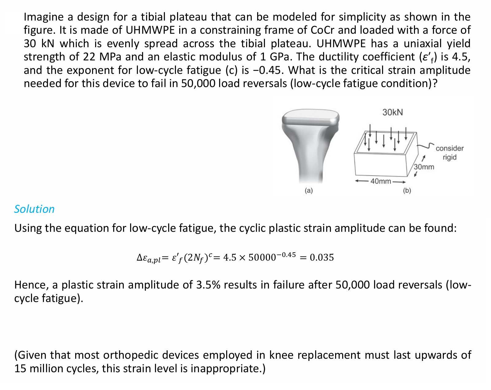
- Tests with high plastic strains are low-cycle fatigue.
- has relatively small number of cycles to failure.
- Δεa≈Δεa,pl 弹性形变可忽略,主要是塑性形变
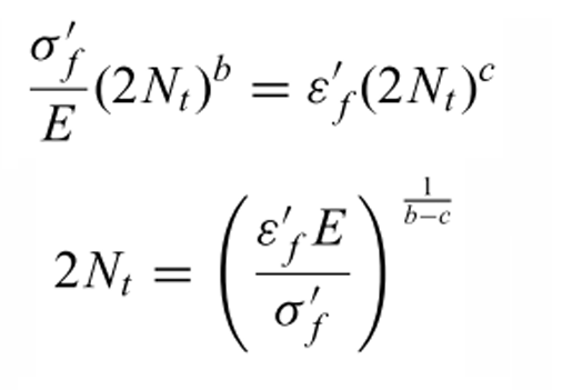
- Transition cycles are found by equating elastic and plastic strain amplitudes and solving for Nt.
- high-cycle fatigue
- example
- 图
- 图
- Use Cases
- Design Methodologies for Medical Devices
- 图
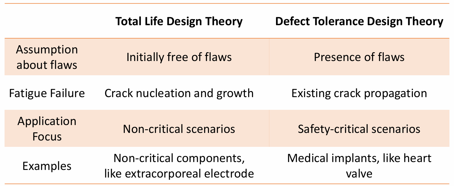
- Total Life Philosophy 全寿命
- The total life design methodology assumes that the component is initially free of flaws sufficiently sized for growth or ideally the component is defect-free.
- Fatigue failure is consequence of crack nucleation and subsequent growth to a critical size
- The majority of life is spent in the nucleation or initiation phase.
- Total life characterization is based on
- stress-based test over stress amplitudes and mean stress
- strain-based test under cyclic strain amplitudes
- Defect-Tolerant Philosophy
- The fatigue life of a component is based on the number of loading cycles needed to propagate an existing crack to a critical dimension.
- The initial size of the flaw is assumed to correspond to the resolution of an inspection test.
- The critical dimension of the flaw is directly correlated to fracture toughness of the material.
- The defect-tolerant approach is used in safety-critical applications, such as heart valve designs.
- 图
- Fatigue Definition
- Take-Home Message
- What is the difference between ductile and brittle materials?
- Ductile materials yield before fracture and generally deform through shear.
- Brittle materials fracture before yield and are weak in tension.
- How to use maximum shear stress theory to predict yield in 3D condition?
- Compute the three principal stress differences.
- τmax = MAX{|σ1 - σ2| / 2, |σ2 - σ3| / 2, |σ1 - σ3| / 2}
- Compare τmax with σyp / 2.
- What is stress concentration?
- Local stress amplification caused by geometric discontinuities such as holes, cracks, scratches, notches, or sharp force application.
- σmax = kt σbar
- What is fatigue?
- Fracture due to repeated loading.
- Failure can occur below yield or ultimate tensile strength after enough cycles.
- What are low-cycle fatigue and high-cycle fatigue?
- Low-cycle fatigue: large plastic strains and low number of cycles, about Nf = 1 to 10^3.
- High-cycle fatigue: mostly elastic deformation and high number of cycles, Nf > 10^3.
- What is the endurance limit?
- The cyclic stress level that enables infinite life in the material.
- Most steels have endurance limit around 35-50% of ultimate tensile strength.
- What is the difference between ductile and brittle materials?





All articles in this blog are licensed under CC BY-NC-SA 4.0 unless stating additionally.